Incorrectly positioning drive and take-up units doesn't just cause premature wear. It fundamentally jeopardizes operational uptime and voids equipment warranties. Poor placement rapidly turns an efficient manufacturing facility into a continuous maintenance nightmare. For facility engineers and operations managers finalizing a layout, precise component placement matters immensely. This engineering decision forms the exact difference between a smooth-running line and chronic chain surging. You must balance system tension points accurately to keep daily production flowing without unexpected stops. This guide details the critical engineering realities and stringent layout rules required to correctly site your drive and take-up components. You will learn exactly how to position these units to ensure system longevity and minimize maintenance overhead. We explore practical strategies to optimize your industrial setup. By following these proven guidelines, you prevent costly breakdowns and maintain peak operational efficiency.
Key Takeaways
Drive Unit Placement: Must be located at the point of maximum chain tension, typically preceding the largest load or longest run.
Take-Up Unit Placement: Must follow immediately downstream of the drive unit at the point of minimum tension to absorb slack effectively.
System Integrity: Misalignment introduces chain surge, rapid track wear, and potential motor burnout.
Capacity Considerations: Upgrading from standard configurations to heavier models (like the ETC 7000 Series Conveyor) requires recalculating friction and tension loads for optimal placement.
The Operational Cost of Poor Unit Placement
Improper layout design triggers a cascade of mechanical failures. Systems often fail prematurely when designers place drive components based on spatial convenience rather than structural physics. Ignoring established engineering rules guarantees system instability. Drive and take-up units dictate the operational rhythm of your entire facility. Placing them incorrectly forces the machinery to fight against its own operational design.
Chain Surging & Pulsation
Placing a drive unit at a low-tension point causes immediate mechanical distress. The chain bunches up right before engaging the drive gears. This unnatural bunching creates a highly destructive phenomenon known as chain surging. Surging causes jerky, erratic movements across the entire production line. Suspended products sway wildly. They bump into surrounding structures or collide against each other. Fragile parts drop. Expensive surface finishes scratch. Chain pulsation disrupts automated paint lines and robotic assembly stations, rendering precise automated tasks impossible.
Accelerated Component Wear
Unmanaged slack dramatically accelerates wear across every moving part. When slack gathers in the wrong zones, friction multiplies exponentially. The chain drags heavily against the inner track. Bearings endure extreme lateral stress they were never engineered to handle. The enclosed track walls suffer deep gouges from misaligned chain links. Rapid component wear forces your maintenance teams into a constant state of firefighting. You will replace drive sprockets and corner wheels far ahead of their scheduled lifespan.
Defining Layout Success Criteria
You can identify a successful layout through a few specific operational metrics. First, the chain pull remains perfectly consistent. Second, the take-up carriage exhibits minimal movement during standard operation. It should only adjust slightly for gradual wear or thermal changes. Finally, maintenance cycles remain highly predictable. You achieve this mechanical harmony only through objective, mathematically verified component positioning.
Engineering Rules for Siting Drive Units in an Overhead Conveyor System
Every Overhead Conveyor System demands precise drive placement. Engineering principles dictate exact locations for maximum efficiency. You cannot guess these locations. You must calculate them based on your facility's unique friction and load dynamics.
The Rule of Maximum Tension
The most critical engineering rule states you must pull the load, never push it. Drive units must sit at the exact point of maximum chain tension. Engineers typically locate the drive just after the system's most demanding elevation change. Alternatively, they place it immediately after a high-friction curve cluster. Siting the drive here guarantees the motor pulls effectively against the heaviest resistance point. Pushing a chain through a curve instantly causes track binding and structural deformation.
Straight Track Requirements
You must install drive units on a completely straight section of track. We recommend a strict minimum of 3 to 5 feet of straight track entering the unit. You need an identical straight length exiting the unit. Curved approaches cause lateral chain binding. When the chain enters the drive sprocket at an angle, it creates uneven gear wear. This misalignment significantly increases the risk of catastrophic chain jams and drive shear pin failures.
Multi-Drive Synchronization Criteria
Single drives fail when layouts exceed specific length limits or total pull-weight capacities. Massive automotive or appliance lines often require multi-drive configurations. However, synchronizing multiple drives introduces immense mechanical complexity. You must evaluate the following criteria before adding a second drive:
Load Sharing Limits: Can the primary drive handle 60% of the total friction load?
Speed Synchronization: Variable Frequency Drives (VFDs) must communicate flawlessly to match exact pull speeds.
Motor Burnout Risks: If synchronization fails, one motor drags the dead weight of the other.
Maintenance Accessibility
Engineers sometimes forget the physical footprint of the equipment. You must ensure maintenance crews can easily reach the drive unit. Can technicians access it safely via manlifts or catwalks? Routine motor replacements, gearbox oil changes, and torque limiter adjustments require safe access. Never hide a drive unit in a tight ceiling corner above active production machinery.
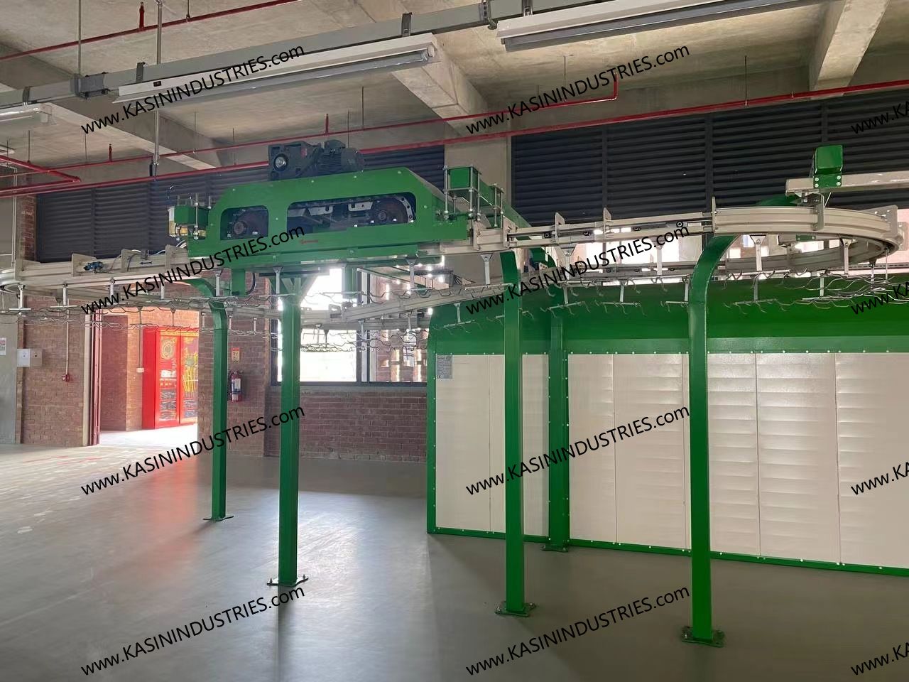
Positioning Take-Up Units to Manage Chain Slack
The take-up unit serves as the shock absorber for your entire line. It manages the inevitable slack generated by motion, wear, and temperature fluctuations. Correct placement here prevents chain bunching downstream.
The Rule of Minimum Tension
The rule of minimum tension dictates your take-up placement strategy. You must place the take-up unit immediately after the drive unit. It must sit downstream. The drive unit creates tight tension behind it and loose slack directly in front of it. The take-up unit exists solely to gather this localized slack. If you place it anywhere else, slack travels unchecked through your facility.
Functionality in Reality
Take-up mechanisms compensate for two unavoidable physical realities: natural chain stretch and thermal expansion. Chains wear down over years of use. Internal pins and links elongate slightly. Across hundreds of feet, this microscopic elongation creates massive overall slack. Furthermore, thermal expansion plays a major role. Conveyors passing through high-temperature curing ovens experience significant metal expansion. The take-up unit dynamically expands and retracts to manage these structural changes.
Table 1: Comparison of Take-Up Unit Mechanisms
| Mechanism Type | Primary Application | Maintenance Needs | Tension Adjustment |
| Spring-Loaded | Light loads, ambient temperatures, shorter layouts. | Low. Requires occasional manual spring re-tensioning. | Passive and fixed. |
| Air-Regulated (Pneumatic) | Heavy loads, oven passages, dynamic thermal environments. | Medium. Requires clean, dry compressed air supply. | Active and continuous. |
Layout Traps to Avoid
Facility designers frequently fall into common layout traps. You must never place horizontal curves between the drive and the take-up unit. Do not install elevation dips or inclines in this zone either. These track features trap chain slack. Trapped slack defeats the purpose of the take-up unit completely. The chain will eventually surge, bind, and tear the track off its ceiling mounts.
Evaluating Component Specs: Enclosed Track Conveyor Configurations
Specific hardware models dictate your layout tolerances. You must balance your expected product load against your facility's spatial limitations. Every Enclosed Track Conveyor carries unique engineering restrictions.
Light-to-Medium Duty Tolerances
For standard manufacturing environments, we typically specify lighter setups. The ETC-5000 Conveyor System handles standard assembly line constraints beautifully. However, you still need precise unit placement. Standard duty does not mean you can ignore tension rules. A lightweight system will still surge if you place the drive before a massive elevation dip. You must calculate friction coefficients accurately even for 50-pound pendant loads.
Heavy-Duty Applications
Heavy-duty applications demand an entirely different level of scrutiny. When you specify an ETC 7000 Series Conveyor, tension management becomes hyper-critical. Heavier loads amplify the physical risks of poor component positioning. A minor layout error on a heavy-duty line causes massive structural stress. The friction calculations become stricter. The structural supports require heavier gauge steel. You cannot cut corners on straight track approaches when pulling thousands of pounds of cast iron parts.
Vendor Claims vs. Engineering Reality
Always verify vendor marketing claims against harsh engineering reality. Some salespeople promise their drive units can push loads through complex curves. Engineering physics proves otherwise. Buyers must demand verified tension calculations. Ask your vendor to use proprietary software for load modeling. Follow these best practices when evaluating vendor claims:
Request a detailed chain pull calculation report before purchasing.
Demand a 3D simulation of the proposed track layout.
Verify the safety factor built into the maximum load ratings.
Hire an independent structural engineer to review the proposed header steel design.
Implementation Risks and Pre-Installation Verification
Skipping pre-installation checks guarantees disastrous results during commissioning. You must treat the installation phase as a rigorous scientific exercise. Gather your technical team to verify every dimension and capacity limit before ordering parts.
Friction and Pull Calculations
Walk through the necessity of running a rigorous chain pull calculation. You cannot guess where the tension builds up. You must objectively identify maximum and minimum tension points using friction coefficients. Every curve adds friction. Every incline multiplies the load factor. You add these numbers together to find your peak tension zone. The drive unit goes exactly there. The calculations will also reveal if a single drive can handle the total line resistance.
Structural Support Realities
Remind decision-makers about gravity. Drive units represent the absolute heaviest point of the entire system. A single heavy-duty drive package can weigh hundreds of pounds. You must verify your roof steel capacity. If your roof cannot support the load, you must design floor-supported header steel. The structure must support the static weight of the machinery. More importantly, it must withstand the dynamic torque generated when the motor starts and stops under full load.
Shortlisting Next Steps
Technical buyers should formalize their evaluation process. Request a documented layout review from potential vendors. A credible manufacturer will push back on a flawed CAD drawing. They will explain why your proposed drive placement violates engineering principles. Reputable engineers refuse to just sell parts for a doomed layout. Look for partners who prioritize operational success over a quick hardware sale.
Conclusion
Positioning drive and take-up units remains an objective engineering science, not a matter of spatial convenience. Ignoring the rules of maximum and minimum tension guarantees premature component failure. By placing the drive before the heaviest load and the take-up immediately downstream, you secure a smooth-running line. You prevent chain surging, protect your suspended products, and drastically reduce your daily maintenance requirements.
Your next actionable step involves validation. Stop guessing about component placement. Submit your current CAD layout or facility floor plan to a qualified manufacturer for an expert engineering review. Let a professional run the chain pull calculations. Transition from the evaluation phase to a confident project kickoff by securing a mathematically verified layout design today.
FAQ
Q: Can the drive and take-up unit be combined into one section?
A: Yes, combination drive/take-up units exist for specific compact layouts. Manufacturers design them to save space in tight facilities. However, they have strict limitations on total chain pull, suspended weight, and overall system length. They are generally unsuitable for heavy-duty applications or long, complex routing.
Q: How much straight track is required before a take-up unit?
A: You typically need a minimum of 2 to 3 feet of straight track entering the take-up unit. This straight approach ensures the chain enters the expansion joint smoothly without lateral binding. Skipping this straight section causes rapid wear on the take-up carriage wheels.
Q: What happens if my conveyor passes through an oven?
A: High temperatures cause significant metal expansion across your chain and track. The take-up unit must possess enough travel distance to absorb this thermal stretch. For oven applications, engineers highly recommend pneumatic (air-regulated) take-ups for dynamic, continuous tension adjustment.
Q: How do I know if I need more than one drive unit?
A: You base this decision on the maximum allowable chain pull for your specific track model. If your calculated friction and suspended load exceed the continuous duty rating of a single drive motor, you must install a multi-drive configuration. Synchronized VFDs are required to manage them.