Pinpointing the exact line speed for an overhead conveyor system is rarely a matter of maximizing motor output. It requires balancing operational throughput, physical process constraints, and the mechanical limits of the hardware. Processes like curing, washing, and robotic assembly all dictate specific timing rules. Operations teams must harmonize these rules before turning a single drive shaft.
Overestimating speed leads to premature track wear, product sway on inclines, and safety hazards. Parts might swing and collide, causing significant product damage. Underestimating speed creates facility-wide bottlenecks and missed production quotas. You cannot afford to guess the velocity of your production line.
We aim to provide engineering and operations teams with a concrete framework. You will learn to calculate, evaluate, and select the correct speed and drive type for your facility's specific load and layout. This guide breaks down the math, hardware constraints, and integration strategies necessary to engineer a reliable system.
Key Takeaways
Conveyor speed is a dependent variable dictated by production rate (parts per hour) and carrier pitch, not just drive capacity.
Different architectural designs (e.g., continuous monorails vs. accumulation systems) possess drastically different speed thresholds.
Variable Frequency Drives (VFDs) are the industry standard for future-proofing systems against changing throughput requirements.
Factoring in product sway, chain wear, and robotic integration tolerances is non-negotiable for system longevity.
Defining the Baseline: Throughput Goals vs. Process Times
Speed cannot be calculated in a vacuum. It must serve the facility's macro throughput targets while respecting micro process limits. Engineers often assume they need the fastest motor available. In reality, line speed acts as the metronome for the entire production floor. You must balance the raw demand for product volume against the rigid realities of physical manufacturing processes.
Defining the exact number of units passing a specific point per hour, shift, or day is your primary throughput requirement. If your facility needs to ship 1,000 units per shift, you work backward from this number. We call this the macro goal. However, macro goals easily crash into micro constraints on the production line.
Factoring in fixed-time operations is critical. Consider a powder coating application. If a part requires a 20-minute dwell time in a curing oven, the speed must allow the carrier to remain in the oven zone for exactly that duration. If the line runs too fast, the paint will not cure properly. If it runs too slow, the part bakes and ruins the finish. Process engineers must measure the physical length of the curing oven and calculate the exact feet per minute (FPM) required to achieve the 20-minute dwell time.
Finally, we must assess manual loading and unloading zones. Safe manual interaction typically caps continuous line speeds at 10 to 15 FPM. Human operators cannot safely hook or unhook heavy loads moving at 30 FPM. Ergonomic limits dictate these zones. If your macro throughput goal requires a speed faster than 15 FPM, you will need to rethink your system architecture or carrier density.
The Core Equation: Calculating Your Required Line Speed
System integrators rely on a standard calculation framework to determine baseline line speed. We never pull FPM numbers out of thin air. Instead, we use a simple, reliable mathematical formula to dictate our hardware parameters.
The Base Formula
The standard equation is straightforward: Speed (FPM) = (Desired Parts Per Minute × Carrier Pitch) / Parts per Carrier. This formula reveals how carrier density and spacing directly control the required velocity.
Variable Breakdown
To use this equation accurately, you must define the following variables:
Desired Parts Per Minute: Convert your hourly or shift-based throughput goals into a per-minute metric.
Carrier Pitch: This represents the exact physical distance between carrier attachment points on the conveyor chain. A closer pitch means carriers travel closer together.
Parts per Carrier: This measures the density of the load. A multi-tier rack holding ten small parts requires far less line speed than single, heavy items spaced far apart.
Once engineers calculate the theoretical speed, they typically add a capacity buffer. We usually add a 10% to 15% margin to the calculated speed. This buffer accounts for standard maintenance downtime, micro-stoppages, and operator breaks. It also leaves room for future throughput scaling without requiring an immediate mechanical overhaul.
Conveyor Speed Calculation Scenarios
| Scenario Type | Parts Per Minute | Carrier Pitch (Feet) | Parts Per Carrier | Base Speed Required (FPM) | Speed with 15% Buffer (FPM) |
| High-Density Load (Small Parts) | 20 | 2 | 4 | 10 FPM | 11.5 FPM |
| Low-Density Load (Large Parts) | 20 | 4 | 1 | 80 FPM | 92.0 FPM |
| Heavy Assembly (Slow Pace) | 5 | 6 | 1 | 30 FPM | 34.5 FPM |
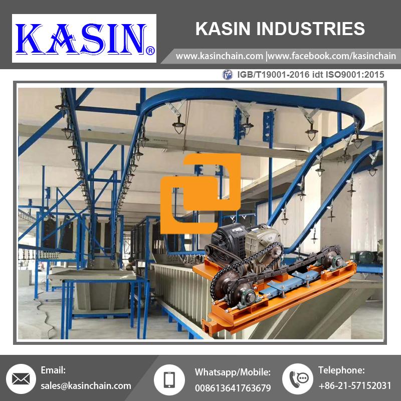
Hardware Constraints: Matching Speed to System Architecture
Not all overhead systems handle velocity equally. Selection must align directly with the structural capabilities of the chosen track and chain style. Pushing a lightweight track to high speeds will result in catastrophic failure, while underutilizing a heavy-duty system wastes significant capital.
Standard Enclosed Track Systems
Enclosed track setups are best for continuous, uniform motion. They typically optimize operations for moderate speeds ranging from 1 to 60 FPM, where loads remain consistent and routing is relatively straightforward. For robust reliability in these scenarios, integrators frequently specify a P56 Monorail Conveyor. This style encloses the chain, protecting it from environmental debris while safeguarding operators from moving pinch points.
If your facility requires a slightly different layout but still demands a closed track profile, the ETC7000 Overhead Conveyor is another excellent standard. Both systems thrive when the entire line moves at one synchronized speed. However, they do not allow parts to stop independently.
Asynchronous Operations
Manufacturing rarely flows in perfect continuity. Sometimes you need complex layouts requiring variable speeds within the very same system. This is where a Power & Free Conveyor becomes essential. This architecture allows high-speed transport between distant zones, but enables slowing down or complete accumulation at robotic cells and manual workstations.
In a Power & Free system, the "power" chain runs continuously. The "free" trolleys carry the load and can disengage from the moving chain. This means you can run your transport zones at 60 FPM, but stop the load entirely for a worker to perform a 3-minute assembly task.
High-Precision Environments
Some industries have zero tolerance for swinging parts or falling debris. These high-precision environments include cleanrooms, automotive paint lines, and robotic assembly cells. Here, engineers deploy an Inverted Monorail Conveyor. By flipping the track upside down and mounting it to the floor or lower framework, the load sits securely on top.
This design strictly constrains speed by the requirement for zero load sway and high positional accuracy during robotic interaction. Because the product rides on top of a rigid pedestal, robots can interact with the parts without waiting for swinging motion to settle. The velocity profile here prioritizes absolute smoothness over raw speed.
Implementation Risks: The Cost of Incorrect Speed Calibration
Choosing an arbitrary speed invites a cascade of mechanical and operational failures. When an Overhead Conveyor System runs faster than its intended engineering limits, the laws of physics aggressively take over.
Centrifugal force causes serious product sway. When a carrier enters a horizontal curve at high speeds, the load wants to continue straight. This causes the parts to swing outward. Excessive speed on horizontal curves or vertical elevation changes causes product collision. In paint lines, this sway leads to uneven coating thicknesses. In assembly areas, swinging components become severe dropping hazards, threatening employee safety.
Accelerated mechanical wear is another direct consequence. There is an exponential relationship between high speed and chain/track degradation. Faster speeds require significantly more frequent lubrication. They dramatically reduce the lifespan of drive sprockets and track curves. The friction generated by high-speed metal-on-metal contact will quickly erode standard bearings.
Furthermore, incorrect speeds cause data and tracking failures. Modern facilities use rotary encoders to measure line speed dynamically. This is vital for synchronized robotic picking. However, excessive speeds or track vibration can lead to encoder skipping. When the encoder misses pulses, the PLC loses positional data, causing robotic arms to miss their targets entirely.
Finally, we must consider drive overload. Undersizing the motor and gearbox for a high-speed, high-load application guarantees trouble. Pushing a small motor to move heavy loads quickly results in thermal overload. The motor bakes itself from the inside out, leading to premature failure and sudden line stoppage.
Future-Proofing: Variable Frequency Drives (VFDs) vs. Fixed Speed
Once you calculate your required speed, you must decide how to power the chain. Historically, engineers used basic direct-on-line motors. Today, modern facilities demand much greater control.
Fixed speed drives offer a lower initial capital expenditure, but they remain extremely rigid. We only recommend them for dedicated, single-purpose lines that will never change capacity. If you install a fixed-speed drive, your line runs at one speed forever. To change the speed, mechanics must physically swap out the gearbox or drive sprockets.
VFD integration represents the industry standard for modern facilities. A Variable Frequency Drive alters the electrical frequency supplied to the motor, allowing precise speed control via a digital interface.
Scalability: VFDs allow operators to dial the speed up or down based on shift demands, seasonal volume, or changing product mixes.
Ramp Up and Ramp Down: VFDs prevent jarring starts and stops. By programming a soft start, you eliminate the mechanical jerk that damages conveyor chains and drops fragile products.
Energy Efficiency: A VFD matches the motor power draw precisely to the required load and speed. It reduces unnecessary electrical consumption, easing the burden on your facility's power grid.
Shortlisting Your Integrator: Evaluation Criteria
You should never design a line alone. Partnering with a skilled integrator guarantees your math translates safely into physical hardware. However, not all integrators apply the same level of engineering rigor.
Evaluate their validation capabilities carefully. Do they use dynamic load simulation software to model product sway and chain pull at your target speed? Ask them to show you the calculated chain pull for your specific layout. If they rely on guesswork, find another partner.
Component transparency matters immensely. Are they specifying standard, accessible drive components? Some integrators lock you into proprietary, hard-to-source gearboxes. You want systems that utilize standard motors and VFDs so your maintenance team can source replacements locally during an emergency.
Question their approach to compliance and safety. Do they implement fail-safes like torque limiters and shear pins? These mechanical fuses must be scaled specifically to the system's mass and maximum velocity. If a jam occurs, a properly sized shear pin will snap, disconnecting the motor before it tears the track from the ceiling.
Your next step is requesting a facility audit. Ask the integrator for an engineered layout draft that includes calculated pitch parameters and proposed FPM metrics. Demand to see the math.
Conclusion
Selecting conveyor speed is a foundational engineering decision. It dictates hardware selection, guarantees facility safety, and defines your overall operational efficiency. You cannot isolate line speed from process times, carrier pitch, or load density.
Avoid making speed assumptions based solely on a motor's maximum output. Calculate backward from your strict throughput requirements and physical process constraints. Prioritize systems equipped with Variable Frequency Drives for ultimate operational agility. By securing precise speed calibration, your production line will run smoothly, predictably, and safely for years to come.
FAQ
Q: How do you accurately measure conveyor speed on an existing line?
A: The most accurate method involves using a rotary encoder integrated into the drive shaft or idler wheel. The encoder sends digital pulses to a PLC, translating rotation into feet per minute (FPM). For spot-checking, maintenance teams use handheld laser tachometers aimed at a reflective marker on the moving chain to get an instant FPM readout.
Q: What is the maximum safe speed for a standard overhead conveyor system?
A: While robust enclosed track systems can technically achieve speeds of 60 to 100 FPM, practical limits are lower. Any zone requiring manual loading or unloading must operate below 15 FPM for ergonomic safety. High-speed runs are reserved purely for transport zones between automated processes.
Q: Can I increase the speed of my current overhead conveyor without upgrading the motor?
A: It is highly risky. Increasing speed via a VFD on a legacy motor alters the torque profile and chain pull limits. You may exceed the existing gearbox ratio limits, causing thermal overload. Always recalculate the total chain pull and verify the motor's horsepower rating before adjusting the frequency.
Q: How does carrier pitch affect my required conveyor speed?
A: They share an inverse relationship. A closer carrier pitch allows you to transport more parts per foot of chain. Consequently, you can run the line at a slower, safer speed while still maintaining the exact same hourly throughput goals. Wider pitches demand faster line speeds.