Specifying the wrong chain pitch in an overhead conveyor system does not just cause premature wear. It leads to catastrophic line stoppages and seriously compromises product handling. You must get this baseline metric right. Chain pitch is the center-to-center distance between consecutive chain pins. We consider it the foundational variable for all system engineering. It dictates how every subsequent component fits together. A fractional mismatch propagates errors across thousands of feet of track.
This guide provides a technical, engineering-backed framework for selecting the correct chain pitch. We base our evaluation on load profiles, routing geometry, and maintenance targets. You will learn how to match pitch lengths precisely to your operational realities. We cover chordal action, layout constraints, and specific hardware requirements. Our goal is to equip you with actionable selection logic to prevent costly design failures.
Key Takeaways
Chain pitch directly dictates minimum turning radii, sprocket engagement (chordal action), and allowable pendant spacing.
Short pitches offer smoother operation in tight curves, while longer pitches handle heavier point-loads and reduce total component count over long runs.
System architectures—such as an Enclosed Track Conveyor 7000 Series versus a heavier P56 Monorail Conveyor—strictly limit pitch options based on track constraints.
Accurate pitch selection requires calculating total chain pull and mapping it against the required sprocket sizes to prevent premature elongation.
Why Chain Pitch Determines System Viability (Success Criteria)
Chain pitch directly dictates your conveyor's physical flexibility. We see a strict inverse relationship between pitch length and system agility. Shorter pitches bend easily around tight corners. They articulate smoothly. Longer pitches demand much broader curves. They act like rigid levers through a turn. If you ignore this basic physics principle, you risk immediate mechanical failure. Shorter pitch chains wrap tightly around sprockets, creating a highly continuous motion. Long pitch chains require much more room to articulate. You must physically match the chain's flexibility to your building's architectural constraints.
Next, consider chordal action. Engineers often call this the polygon effect. Pitch length heavily affects operational smoothness over sprockets. Longer pitches create significantly higher chordal action. The chain rises and falls as pins engage the sprocket teeth. This motion leads to noticeable pulsation in the line. It also accelerates wear if you do not properly compensate. Engineers usually solve this by increasing sprocket diameters. Larger sprockets flatten the polygon effect significantly. They distribute the chain tension over a wider rotational arc. This effectively minimizes the bouncing effect. However, larger sprockets demand much more physical headroom in your facility.
Pitch also establishes strict increments for load attachment. We call this allowable pendant spacing. You must attach loads at intervals matching the pitch perfectly. Mismatched load spacing poses severe risks to your infrastructure. It often causes track flaring over time. It can also lead to severe chain binding inside the enclosed track. You must align your point loading strategy perfectly to your selected pitch. If your product requires a hook every 12 inches, your pitch must mathematically support that spacing without awkward offsets. For example, a 3-inch pitch easily divides into 12 inches. A 5-inch pitch does not. You will face constant headaches trying to adapt incompatible attachment points.
Core Evaluation Dimensions for Pitch Selection
Evaluating your application requires a structured, mathematical approach. You must look at four distinct dimensions before making a final selection.
Load Weight and Distribution (Payload Geometry)
First, calculate the maximum point load against the distributed load. Heavy, concentrated payloads demand robust support structures. You cannot treat them like evenly spread-out goods. You must address the limits of single-point suspension. Single points take the entire brute force of a heavy part. Multi-point suspension spreads these forces across multiple chain pins. This reduces localized stress significantly. It prevents premature pin deformation under heavy strain. You must ensure the chosen pitch supports the required pendant attachments without exceeding the ultimate tensile strength of the individual chain links. A heavy engine block requires a vastly different approach than light plastic fascia parts.
Layout Geometry (Horizontal and Vertical Radii)
Track curves introduce rigid physical limitations. The chain must negotiate these curves smoothly without dragging. The minimum allowable radius is mathematically bound by the chain pitch. A long pitch physically cannot navigate a tight 24-inch radius. Attempting this forces mechanical lock-up. You must calculate these bend allowances carefully. Vertical elevation changes also require special attention. Incline and decline angles heavily restrict your maximum pitch length. When a chain travels up a steep incline, it must articulate cleanly without binding against the upper track flange. Long pitches struggle with tight vertical bends.
Operating Speed and Throughput Constraints
Chain velocity directly impacts dynamic friction inside the track. Faster speeds multiply the friction coefficient of longer pitches. You face a hard operational threshold here. High operating speeds almost always necessitate shorter pitches. A shorter pitch reduces structural noise through rapid articulation. It also minimizes damaging vibration levels across the facility. If your line runs fast, keep the pitch short. High-speed systems utilizing long pitches often suffer from rapid chain whip. This whipping motion damages the track and drastically reduces the lifecycle of the entire conveyor framework.
Environmental and Lubrication Factors
Operating environments frequently dictate your pitch choice entirely. Washdown areas and high-heat paint ovens require specialized, resilient components. These harsh zones demand heavy-duty, sealed bearings to survive. Larger bearings physically require longer pitches to fit the housing geometry. You must account for these physical size requirements early. You cannot force a large high-temp bearing onto a miniature chain pitch. Consider the lubrication requirements as well. Some environments restrict the use of wet lubricants. You might need a specific pitch that accommodates self-lubricating polymer components.
Chain Pitch Evaluation Matrix
| Evaluation Dimension | Short Pitch Characteristics | Long Pitch Characteristics |
| Turning Radius | Navigates extremely tight curves | Requires broad, sweeping curves |
| Operating Speed | Supports higher speeds with low noise | Slower speeds required to prevent vibration |
| Chordal Action | Minimal pulsation over sprockets | High pulsation, requires larger sprockets |
| Payload Distribution | Ideal for multi-point, light loads | Ideal for heavy, single-point loads |
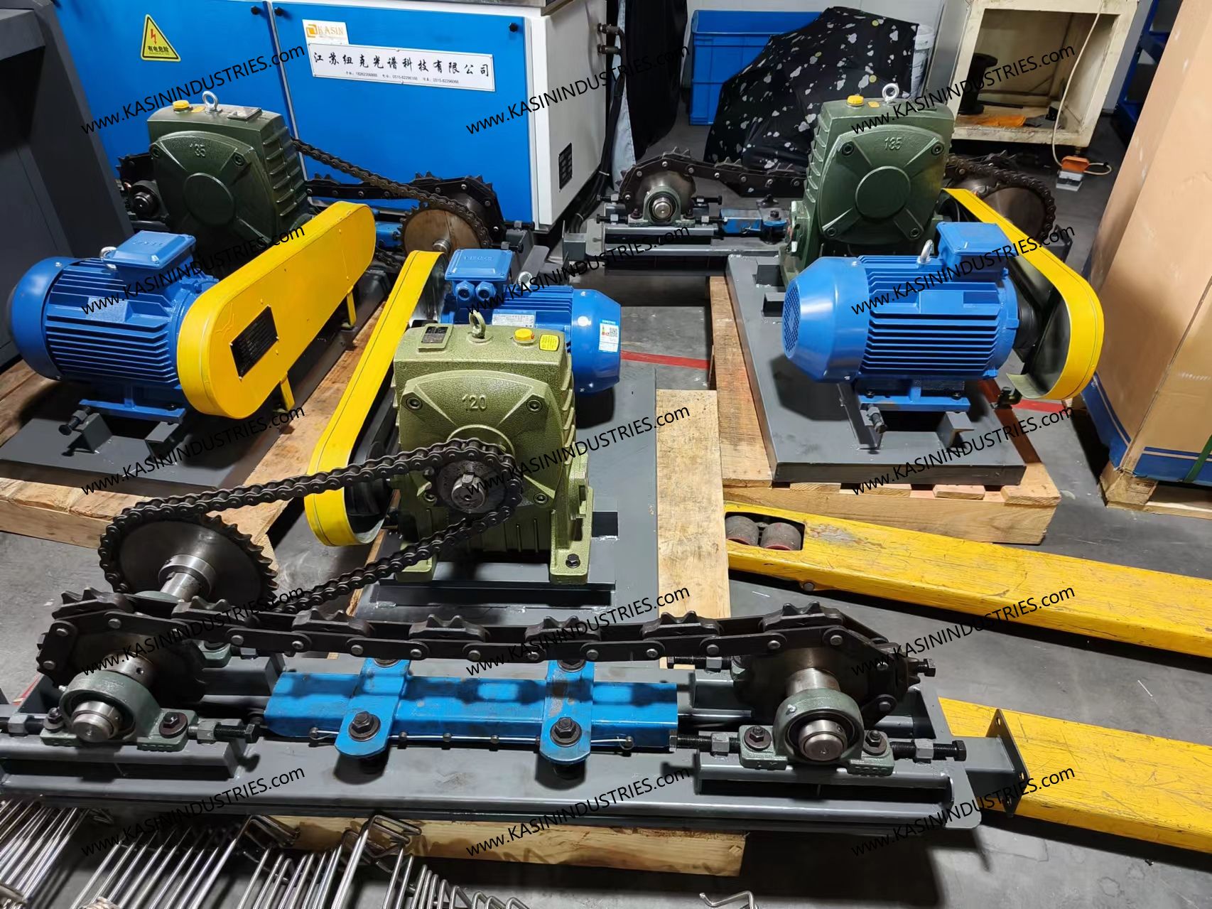
Matching Pitch to Specific Overhead Conveyor Systems
Different architectures demand highly specific chain pitches. You cannot treat them interchangeably. Let us examine four common setups used in modern manufacturing.
First, the Enclosed Track Conveyor 7000 Series relies on a typical short-pitch configuration. We often see a 6-inch pitch standard here. It perfectly suits medium-duty loads in assembly operations. You will find it frequently in clean environments. It easily handles complex routing featuring very tight radii. This system thrives on flexibility and continuous low-vibration movement. It is often the go-to choice for modern lean manufacturing cells.
Next, consider Four Wheel Bi-planar Conveyor systems. The bi-planar design relies on precise pitch increments. These increments allow the internal universal joints to move freely through 3D space. They provide excellent load-balancing characteristics across multiple axes. This proves absolutely vital when navigating steep incline and decline elevation changes. The pitch must accommodate the complex geometry of simultaneous vertical and horizontal bends. If you specify the wrong pitch here, the universal joints will lock up. They will shatter under the immense drive tension.
For truly heavy-duty tasks, we look at P56 Monorail Conveyor architectures. Automotive and heavy finishing plants rely heavily on these structures. They handle high-capacity industrial applications seamlessly. These systems necessitate longer, forged rivetless chain pitches. Common sizes include 3-inch, 4-inch, or 6-inch drop-forged equivalents. These robust pitches handle extreme chain pull dynamically. They easily survive intense tensile stress in rugged environments like foundries or heavy agricultural equipment assembly. The forged construction provides unmatched durability.
Finally, evaluate Power and Free integration closely. Pitch selection must perfectly align with Pusher Dog spacing. This ensures reliable, repeatable engagement between the drive chain and free-trolley load bars. A miscalculated interval brings severe risks to your entire automated line. You will face immediate synchronization failure. The system simply will not transfer loads smoothly between the power and free tracks. The pusher dogs will miss the load bars entirely or strike them at an improper angle. This leads to dropped payloads and catastrophic equipment damage.
The Ripple Effect: Sprocket Matching and Wear Risks
Your pitch selection creates a massive ripple effect across the entire system footprint. It heavily influences sprocket matching and wear factors. You must plan for these mechanical realities early in the design phase.
Let us discuss sprocket diameter realities first. A general rule of thumb governs this mechanical relationship. A sprocket must have an adequate number of teeth to operate smoothly. Engineers usually recommend a strict minimum of 8 to 12 teeth relative to the chain pitch. Larger pitches mathematically require significantly larger sprockets. A massive drive sprocket drastically impacts your factory layout. You must allocate enough structural steel space to house it. You cannot shrink a sprocket just because space is tight. If you try to run a 6-inch pitch chain around a tiny 6-tooth sprocket, the chordal action will destroy the drive unit within weeks.
You must also monitor chain elongation continuously. Wear is inevitable in any moving mechanical system. Industry professionals often call it "stretch." However, this stretch is actually internal pin and bushing wear. The hardened metal grinds away internally over millions of cycles. You need to calculate acceptable percentage wear proactively. Measure this wear over a specific number of pitches during maintenance. Once it hits a critical threshold, replacement becomes absolutely mandatory. Ignoring this leads to snapped chains. A chain does not stretch like a rubber band. The internal clearances increase as the metal wears away. When this accumulated wear exceeds the allowable limit, the chain no longer fits the sprocket teeth correctly. It will begin to jump teeth, causing massive shock loads.
Track wear presents another major component fatigue risk. Selecting a pitch too rigid for the layout causes massive structural problems. The chain physically resists bending through the curves. It transfers this kinetic stress directly to the track walls. The trolley wheels also absorb this aggressive lateral force. They will degrade rapidly and shed debris onto the product below. This is especially problematic in cleanroom or paint line environments. You must ensure the pitch flows naturally through every track profile to minimize this parasitic friction.
Shortlisting Logic and Finalizing the Specification
You need a structured, reliable method to finalize your specification. Follow these strict engineering steps carefully to ensure a robust system design.
Step 1: Map the Maximum Constraints. Identify the heaviest single point load you plan to carry. Locate the tightest required curve in the entire facility layout. Calculate the absolute maximum chain pull of the proposed routing. These three constraints form your operational boundary box. If you exceed any of these limits, you must redesign the layout or upgrade the system class entirely.
Step 2: Cross-Reference with Vendor Data. Compare your mapped constraints against manufacturer-published working load limits. Always check the published radius charts for the specific chain series. Never guess these values based on similar legacy systems. Verify the data against current engineering catalogs. Materials and manufacturing processes change over time. What worked twenty years ago might not align with today's published safety factors.
Step 3: Verification Questions for Integrators. Ask your integration engineers the hard, practical questions. Does the proposed pitch require a sprocket size fitting within the allotted structural steel envelope? What is the estimated lifecycle in continuous hours under our specific payload and environmental conditions? Will this pitch support future line speed increases? You want to design a system that accommodates growth. Do not box yourself into a corner with a chain pitch operating at its absolute maximum capacity on day one.
Chain pitch is never an isolated metric in material handling. It acts as the genetic code of your Overhead Conveyor System. It influences every other mechanical component downstream. You must treat it as the anchor point of your design phase.
Always verify turning radii constraints before finalizing your pitch selection.
Match your pendant spacing exactly to your specific payload geometry.
Prioritize larger sprocket sizes when possible to combat chordal action.
Run comprehensive simulations to identify potential bottleneck zones.
We encourage you to consult with dedicated system engineers. Always run exact chain pull calculations rather than relying strictly on catalog approximations. Actual operating conditions demand precise mathematical validation to ensure long-term reliability and safety.
FAQ
Q: What happens if the chain pitch is too long for an overhead conveyor curve?
A: A mismatched long pitch causes immediate mechanical binding. You experience excessive friction as the chain forces its way around the bend. This leads to severe track flaring and component damage. Eventually, it causes drive unit overload, resulting in dangerous surging and potential motor failure.
Q: How do I accurately measure chain pitch on an existing, worn system?
A: Use the standard engineering method. Measure across multiple pitches under tension, typically spanning about 10 feet. Divide this total measurement by the exact number of pitches in that span. This gives you the average pitch length. You can then assess the wear percentage against the original factory specification.
Q: Can I upgrade to a different pitch on an existing track?
A: Upgrading is rarely a simple drop-in replacement. Changing the pitch typically requires swapping out the sprockets and drive caterpillar chains. You will likely need to adjust the trolley spacing as well. The structural track might remain, but the internal drive components require a complete overhaul.
Q: How does chain pitch affect a Four Wheel Bi-planar Conveyor differently than a standard monorail?
A: Bi-planar chains feature a unique geometry. Their pitch directly determines the flexibility of the internal universal joints. These joints are required for complex vertical and horizontal transitions. A standard monorail only bends in one plane. Bi-planar pitch defines the allowable 3D articulation limits.